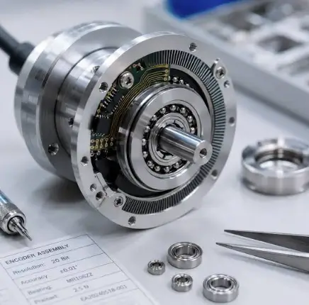
Modern industrial equipment often needs to achieve accurate movement within limited installation space. Robotics, automated production lines, inspection equipment, and specialized positioning systems may require components that support loads while maintaining controlled rotation. Bearing selection becomes particularly important when an assembly must combine compact dimensions, stiffness, and predictable movement.
Crossed roller bearings are designed to address several of these requirements. Their rolling elements are arranged so that adjacent cylindrical rollers are oriented at right angles to one another. This configuration allows the bearing to accommodate loads acting in different directions within a relatively compact assembly.
Although crossed roller bearings offer useful design characteristics, their performance depends on the specific application, manufacturing quality, mounting conditions, and operating environment. Understanding these factors helps engineers select a suitable bearing rather than relying on general product descriptions.
Understanding Crossed Roller Bearing Construction
A crossed roller bearing typically consists of inner and outer rings, cylindrical rollers, separators or spacers, and raceways designed to guide the rolling elements. The rollers alternate in orientation, with each adjacent roller positioned approximately 90 degrees relative to the next.
This arrangement allows the bearing to support radial loads, axial loads from different directions, and overturning moments, depending on its design and ratings. The combined-load capability can reduce the need for multiple separate bearing arrangements in certain applications.
Crossed roller bearings are available in different configurations and dimensions. Some are designed for compact mechanisms, while others are intended for applications that require greater rigidity or specific mounting arrangements.
The appropriate bearing must be chosen according to its documented load ratings, accuracy requirements, operating speed, and installation conditions.
Why Crossed Roller Bearings Are Used
Combined Load Support
Industrial mechanisms can experience forces from several directions at the same time. A rotating platform, for example, may carry vertical weight while also experiencing radial forces and moments generated by an offset load.
A crossed roller bearing can accommodate these combined forces within one bearing arrangement when the design and ratings permit. This may simplify the mechanical layout and help reduce the space required for multiple components.
However, engineers must calculate the expected loads and verify them against the manufacturer’s specifications. The bearing should not be assumed suitable for every load combination simply because it uses crossed rollers.
High Rigidity
Rigidity describes how strongly a mechanical assembly resists deformation under an applied load. In precision machinery, excessive deformation can affect alignment, positioning accuracy, and the quality of the finished operation.
Crossed roller bearings can provide useful stiffness because of their roller arrangement and contact geometry. Actual rigidity depends on bearing dimensions, internal design, preload or clearance, mounting conditions, and the surrounding structure.
The complete assembly must be evaluated when stiffness is important. A rigid bearing cannot fully compensate for a flexible mounting plate or poorly supported housing.
Compact Mechanical Design
In equipment where installation space is limited, combining load-supporting functions into one bearing can help simplify the arrangement.
A compact bearing may reduce the number of separate components required, but designers still need to provide sufficient space for mounting bolts, seals, lubrication, and maintenance access.
The final choice should balance packaging requirements with load capacity, serviceability, and expected operating life.
Applications Across Precision Engineering
Robotics and Automated Machinery
Robotic systems often need controlled movement and repeatable positioning. Bearings in robot joints or rotating assemblies can influence stiffness, friction, and alignment.
Crossed roller bearings may be considered for suitable joints and positioning mechanisms where combined loads and compact construction are important. The final selection depends on the robot’s design, payload, motion profile, and accuracy requirements.
Machine Tools
Machine tools rely on stable mechanical assemblies to maintain consistent machining performance. Rotational mechanisms may require bearings that support loads while limiting unwanted movement.
Engineers should consider the required accuracy, operating speed, thermal conditions, lubrication, and mounting rigidity. The bearing’s performance must remain compatible with the machine’s overall precision requirements.
Inspection and Measurement Equipment
Optical inspection devices, measurement platforms, and laboratory instruments may use rotational mechanisms to position sensors or samples.
These applications can place particular emphasis on smooth movement, low friction, and repeatability. Bearing selection should account for the required positioning accuracy and any sensitivity to vibration or deformation.
Industrial Positioning Tables
Automated production systems sometimes use rotating tables to position parts for assembly, welding, or inspection. A suitable bearing can help support the platform while maintaining the required mechanical alignment.
The expected loads, cycle frequency, and movement pattern should be established before a bearing is specified.
When Customization Becomes Necessary
Standard bearing models can suit many applications, but specialized equipment may have requirements that are not met by an off-the-shelf configuration.
Nonstandard Dimensions
A machine may have a restricted installation envelope or an existing mounting interface that cannot easily be modified. Custom dimensions or mounting features may help address these restrictions.
Any dimensional change must be reviewed against the bearing’s load capacity, raceway geometry, and structural performance. Matching the available space is only one part of the selection process.
Accuracy and Clearance Requirements
Some applications require particular rotational accuracy or limits on internal movement. These requirements should be defined clearly during the design stage.
Engineers should discuss relevant tolerance classes, clearance or preload options, and inspection requirements with the manufacturer. The complete assembly’s stiffness and mounting accuracy should also be considered.
Material and Environmental Requirements
Industrial bearings may operate in environments with dust, moisture, temperature variation, or exposure to specific substances. Material choices, surface treatments, and sealing arrangements can influence suitability.
Any special requirement should be supported by a clear description of the working environment and expected operating conditions. The manufacturer can then assess which options are technically appropriate.
See also: Assessing Color Retention and Material Stability Under Light Exposure
Integration With Existing Equipment
Replacement projects may involve limited access to the original design information. Existing drawings, measurements, identification marks, and photographs can help establish the component’s dimensions and configuration.
Before approving a customized replacement, engineers should verify the relevant load ratings and interfaces. A bearing that fits physically may still differ in internal geometry or performance.
How to Specify a Customized Bearing
A clear technical specification helps reduce misunderstandings during the selection and manufacturing process.
First, define the bearing’s purpose and the movement required. Identify whether the assembly rotates continuously, moves intermittently, or performs frequent positioning cycles.
Next, document the expected radial and axial loads, overturning moments, rotational speed, and operating duty. Where the load changes over time, provide the relevant load profile rather than a single nominal figure.
Then confirm the available installation space, mounting dimensions, required accuracy, and lubrication arrangements. Include details about temperature, contamination, and other environmental conditions.
When discussing LYHGB Bearing customized crossed roller bearings buyers should provide these technical details and confirm the manufacturer’s available design options, specifications, and quality documentation. This helps establish whether a proposed bearing is appropriate for the intended equipment.
Drawings and technical discussions should also clarify inspection criteria, manufacturing tolerances, packaging, and delivery expectations. These details are particularly useful when the bearing forms part of a precision or specialized assembly.
Installation Factors That Influence Performance
Even a carefully selected bearing can underperform if it is installed incorrectly. Mounting surfaces should meet the specified flatness and stiffness requirements, and the installation area should be clean before assembly.
Fasteners must be suitable for the application and tightened according to the manufacturer’s instructions. Uneven clamping can distort the rings or affect internal clearance, which may increase friction or reduce accuracy.
Alignment is especially important in precision systems. The bearing should be installed in a way that avoids unwanted deformation from the housing or connected components.
Where preload or clearance is specified, the installation process should follow the relevant technical guidance. Any commissioning checks should be completed before the equipment begins normal operation.
Maintenance for Consistent Operation
Maintenance requirements vary according to bearing design, workload, environment, and operating frequency. Following the manufacturer’s lubrication schedule helps reduce friction and protect the rolling contacts.
Seals should be inspected for damage, while the surrounding area should be checked for signs of contamination. Unusual noise, vibration, temperature changes, or rotational resistance may indicate that further investigation is required.
For precision equipment, it can be useful to monitor positioning performance and repeatability as part of routine servicing. A change in these characteristics may indicate a problem with the bearing, mounting structure, drive system, or another connected component.
Maintenance records help establish patterns and support timely servicing. When abnormal behavior appears, technicians should investigate the cause rather than assuming that a single adjustment will resolve it.
Frequently Asked Questions
1. What makes crossed roller bearings different from conventional ball bearings?
Crossed roller bearings use cylindrical rollers arranged at alternating right angles. This design can allow them to accommodate radial loads, axial loads, and overturning moments within a compact assembly, subject to the specific bearing ratings.
2. Are crossed roller bearings suitable for precision machinery?
They can be suitable for precision applications where the required stiffness, accuracy, load capacity, and operating conditions match the bearing’s specifications. Installation quality and the rigidity of the surrounding structure also influence performance.
3. What information is required for a customized crossed roller bearing?
Important details include dimensions, load conditions, operating speed, accuracy requirements, mounting arrangement, environmental conditions, and expected duty cycle. Drawings and information about the existing assembly can help the manufacturer assess the design.
Conclusion
Crossed roller bearings provide a compact approach to supporting combined loads in selected precision and industrial applications. Their alternating roller arrangement can offer useful rigidity and simplify mechanical layouts where space and controlled movement are important.
Successful selection depends on accurate load calculations, verified dimensions, clear accuracy requirements, and suitable mounting conditions. By working from a detailed technical specification and following the manufacturer’s installation and maintenance guidance, equipment designers can improve the reliability and consistency of their rotational systems.
